


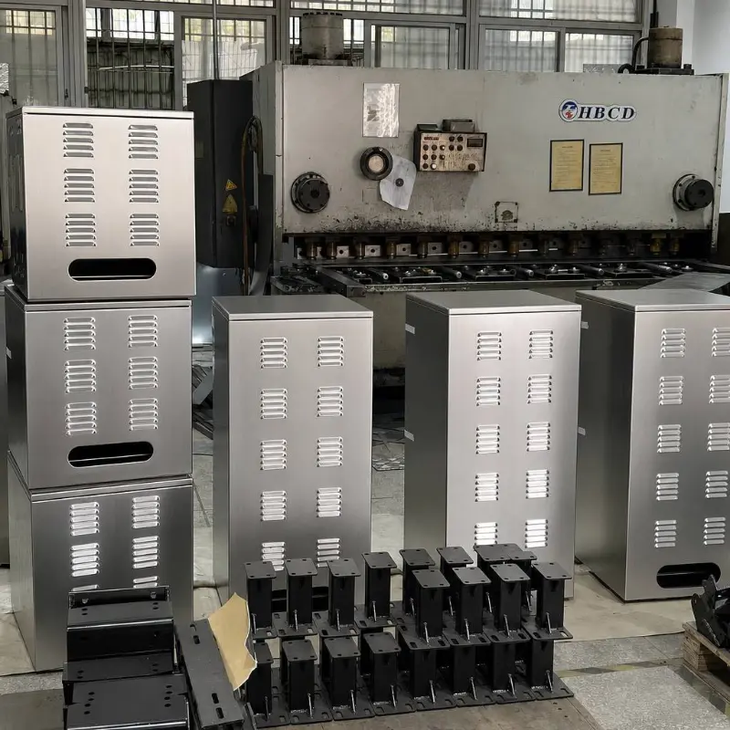

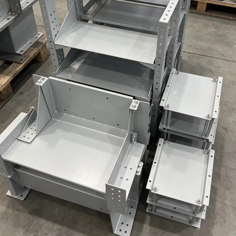
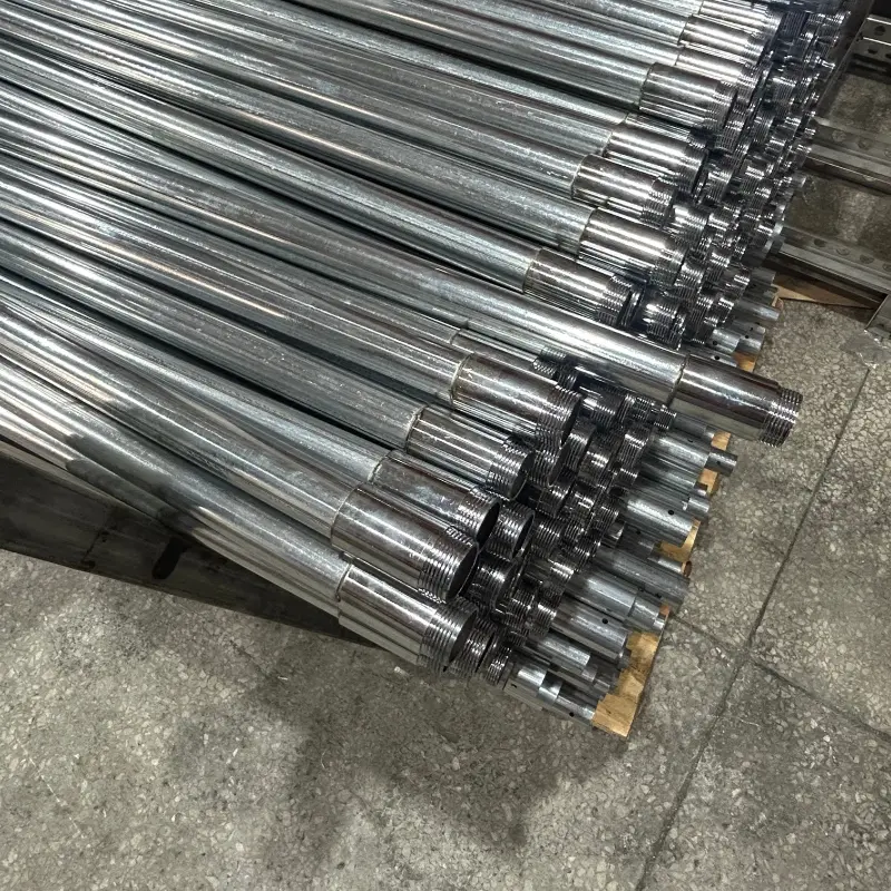
A Metal Electrical Box is far more than a steel shell around wire connections. It is a grounding path, a physical barrier, a heat-tolerant enclosure, and a code-critical component that determines whether an electrical system performs reliably for decades or becomes a service call waiting to happen. This guide explains how metallic enclosures work, how to select the right type and size, how installation and bonding differ from plastic-box practice, and which mistakes most often undermine safety.
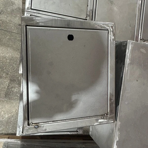
- What a Metal Electrical Box Actually Does
- Types and Material Choices
- Sizing and Box-Fill Essentials
- Step-by-Step Installation
- Grounding and Bonding
- NEMA and IP Ratings
- Common Mistakes to Avoid
- Maintenance and Corrosion Control
- Frequently Asked Questions
Tap any section title above to navigate directly to that heading.
What a Metal Electrical Box Actually Does
A metallic enclosure serves several functions that are easy to overlook until something fails. It holds conductors and devices in a fixed, accessible location, protects splices from mechanical damage, and contains sparks or heat events so they cannot reach surrounding combustible material. In circuits that use metallic conduit, armored cable, or metal-clad cable, the box also completes the grounding path — a role that plastic enclosures cannot perform in the same way.
The practical difference shows up in three areas:
- Mechanical durability: Steel and cast-metal enclosures resist impact, crushing, and deformation far better than polymer boxes, which matters in commercial corridors, industrial bays, and any location where the box may be struck by equipment or personnel.
- Fire and heat tolerance: Metal does not melt, warp, or contribute fuel in the way some plastics can under fault conditions.
- Electromagnetic shielding: A grounded metal enclosure attenuates external RF and electromagnetic interference, which can be useful around controls, instrumentation, and communication equipment.
That combination explains why metallic boxes remain the default specification anywhere the wiring method is metallic, the environment is demanding, or the grounding path must be mechanically robust. A Metal Electrical Box is not a universal replacement for every plastic box, but it is the reference point against which other enclosure choices are measured.
Types and Material Choices
Not every steel box is the same, and the material decision drives corrosion performance, weight, and installation method. The four families below cover most specification scenarios.
| Material / Type | Typical Finish | Best Environment | Key Trade-off |
|---|---|---|---|
| Galvanized sheet steel | Zinc coating | Indoor, dry, general-purpose device and junction boxes | Excellent baseline corrosion protection; not for direct salt or chemical exposure |
| 304 stainless steel | Brushed or natural | Food processing, washdown, coastal, pharmaceutical | Superior corrosion and chemical resistance; higher material weight |
| 316 stainless steel | Brushed or natural | Marine, chloride-rich, severe chemical service | Maximum corrosion resistance in the stainless family |
| Cast aluminum or iron | Powder coat or hot-dip galvanized | Heavy industrial, hazardous-location fittings, high-impact areas | Very rugged; heavier and often more expensive to specify |
Galvanized steel remains the workhorse for indoor branch-circuit work because the zinc coating provides a sacrificial layer that resists rust during construction and through decades of service. Stainless steel becomes necessary when washdown chemicals, chloride, or continuous moisture are present; grade 316 is the safer specification where chlorides are aggressive. Cast-metal boxes trade weight for impact resistance and are common where conduit fittings must be mechanically locked into a threaded hub.
Form factor matters as much as material
Device boxes, square boxes, octagon boxes, utility boxes, and gangable switch boxes each solve a different mounting problem. A gangable switch box, for example, allows two or more enclosures to be fastened side by side into one multi-gang assembly without cutting a separate opening for each device. Square and octagonal boxes provide more volume and multiple knockout combinations for splices and fixtures, while utility boxes are shallow and intended for exposed work where depth is limited.
Knockout planning
Knockouts are pre-cut discs that can be removed to accept conduit, cable clamps, or connectors. A standard ½-inch trade-size knockout measures roughly ⅞ inch in actual diameter, while a ¾-inch trade size measures about 1⅛ inches — dimensions that are frequently confused with the trade label. Combination knockouts accept either size, which reduces the number of box variants an installer must carry. Every opening that is not used must be closed with a listed plug or knockout seal to preserve the enclosure’s integrity and rating.
Sizing and Box-Fill Essentials
An undersized box is one of the most common — and most preventable — installation defects. The National Electrical Code approach is to calculate the volume required by every conductor, device, fitting, and grounding conductor, then select a box whose marked volume meets or exceeds that total. The volume is usually stamped inside the box; when it is absent, it can be determined by measuring the interior dimensions.
The table below shows representative capacities for common metallic box sizes. Actual permitted conductor counts depend on conductor size, insulation type, and whether devices or fittings are present, so the final check should always follow the box-fill rules for the specific installation.
| Box Trade Size and Type | Approximate Interior Volume | Typical Application |
|---|---|---|
| 4 × 1½ inch square | 21 cubic inches | Single-device or small splice point |
| 4 × 2⅛ inch square | 30.3 cubic inches | Multi-wire splices, receptacle or switch with additional conductors |
| 4 11/16 × 2⅛ inch square | 42 cubic inches | Larger conductor counts, pull points, multi-gang assemblies |
| 3 × 2 × 2¼ inch switch box | Varies by gang configuration | Single switch or receptacle in a stud bay |
A practical rule is to count every conductor entering the box as one volume, count each device yoke as two conductor volumes, and count grounding conductors and cable clamps according to the applicable table. When the arithmetic produces a volume close to the box rating, the next larger size is almost always the better choice. Cramming conductors into a box that is technically at its limit creates heat retention and makes future service work difficult.
Step-by-Step Installation
Metallic box installation is not complicated, but the sequence matters. The steps below reflect common practice for a stud-mounted or surface-mounted enclosure.
- De-energize and verify. Turn off the circuit at the breaker, then confirm absence of voltage with a tester before touching any conductor. This is the single non-negotiable step in every electrical installation.
- Select and mark the location. The box face should finish flush with the wall surface. For exterior or wet locations, choose a position sheltered from direct spray and use a box with the appropriate rating.
- Fasten the box securely. Screws or nails must attach the enclosure to a structural member. A box that is not firmly mounted can move when a device is inserted and may leave live parts accessible.
- Remove only the knockouts that are needed. Use a screwdriver to lever out the pre-cut discs. Install cable clamps or conduit connectors in the opened holes, threading them from the outside of the box.
- Run conductors with adequate free length. Bring cable or conduit into the box through the clamp and tighten the clamp onto the sheath or conduit. Leave enough conductor length to make splices comfortably — at least 6 inches beyond the clamp is a common working allowance.
- Strip and connect. Remove insulation without nicking the conductor. Join grounding conductors first, then make the circuit splices, and secure each connection with an approved connector.
- Bond the box. Attach the equipment grounding conductor to the metal enclosure with a listed grounding screw or clip. This step is covered in more detail in the next section.
- Close unused openings and install the cover. Every unused knockout must be sealed. The cover or device plate must leave no gaps that expose live parts.
Each of these steps affects the next. A box that is poorly fastened, for example, can loosen the cable clamp and strain the conductors. A knockout left open after rough-in can allow debris or moisture into the enclosure long before the cover is installed. Treating the sequence as a system rather than a checklist produces a more reliable result.
Grounding and Bonding: The Part Plastic Boxes Cannot Replace
Grounding is where metallic enclosures earn their reputation. The equipment grounding conductor provides a low-impedance path back to the source so that fault current trips the overcurrent device quickly. In a metal box system, the enclosure itself is part of that path and must be bonded to the equipment grounding conductor with a connection used for no other purpose. A grounding screw, grounding clip, or listed grounding fitting is acceptable; relying on a device screw or a loose clamp is not.
Two details are frequently overlooked. First, the grounding connection must remain effective after the device is installed — paint, powder coating, or corrosion at the contact point can raise resistance. Second, when multiple equipment grounding conductors enter the box, they must be joined together and to the box so that continuity is maintained even if a device is removed. The grounding path is not a formality; it is the mechanism that turns a fault into a cleared circuit instead of a shock hazard.
For circuits using metallic raceway or armored cable, the raceway or armor may serve as the grounding means where the code permits it, but the box-to-conductor bonding connection is still required at the enclosure. This is one reason a Metal Electrical Box is specified wherever the wiring method is metallic: the enclosure and the wiring method are designed to work as one grounding system, not as separate components.
NEMA and IP Ratings: Reading the Enclosure Label
Two rating systems appear on enclosure labels, and they are not interchangeable. NEMA ratings are published by the National Electrical Manufacturers Association and are common in North America; IP ratings follow IEC 60529 and are used internationally. NEMA 250 assesses protection against solids, water, corrosion, and in some types ice formation, while IP codes use two digits — the first for solids and the second for liquids. A NEMA 4X enclosure, for example, adds corrosion resistance that an IP66 rating does not address.
| Rating | Primary Protection Focus | Typical Indoor/Outdoor Use |
|---|---|---|
| NEMA 1 | Indoor use; protection against falling dirt and limited contact | Dry indoor walls and ceilings |
| NEMA 3R | Rain, sleet, and snow; indoor or outdoor | Outdoor service equipment, sheltered exterior locations |
| NEMA 4 / 4X | Windblown dust and water; 4X adds corrosion resistance | Washdown, coastal, and process areas |
| IP66 | Dust-tight and protected against powerful water jets | Harsh washdown and outdoor industrial settings |
The practical lesson is to match the rating to the actual environment rather than to a generic “outdoor” label. A NEMA 1 box installed on an exterior wall in a rainy climate will admit water through the cover and unused openings, regardless of how well the box is fastened. Conversely, a NEMA 4X stainless enclosure in a dry indoor ceiling space may be over-specified. Reading the label and understanding what each rating tests is more useful than choosing the highest number on the shelf.
Common Mistakes to Avoid
Most failures attributed to “bad boxes” are actually installation errors. The following patterns appear repeatedly in inspection reports and service calls.
- Using a box that is too small. Overfilling a box with conductors and devices traps heat and makes secure connections difficult. The box-fill calculation exists precisely to prevent this.
- Leaving knockouts open. An unused opening is an access point for dust, moisture, insects, and — in the case of a live enclosure — a path to energized parts. Every opening must be closed with a listed seal.
- Skipping the grounding connection. A metal box that is not bonded to the equipment grounding conductor may appear to work normally while providing no fault-clearing path. This is one of the most serious defects a metallic enclosure can have.
- Mounting the box loosely. A box that shifts when a plug is inserted or a switch is toggled will eventually loosen the conductors or the clamp. Fastening to a structural member is not optional.
- Mixing fittings and box threads incorrectly. Conduit entries must be made with the correct locknuts and bushings. A fitting that is forced or cross-threaded damages the enclosure and compromises the grounding path.
- Ignoring corrosion at the contact points. Powder coating, paint, and oxidation can insulate the box from the grounding screw. The contact area should be clean and the grounding means listed for the purpose.
Maintenance and Corrosion Control
Metallic enclosures are durable, but they are not maintenance-free. The same properties that make steel strong also mean that a scratched coating or a persistently damp interior can become a corrosion site. A practical maintenance routine focuses on three observations: the condition of the finish, the tightness of the cover and fittings, and the absence of moisture or debris inside the box.
Galvanized surfaces should be inspected for white rust or red rust, particularly at cut edges and knockout openings where the zinc coating is interrupted. Stainless steel should be cleaned with a non-chloride cleaner; chloride-based products can initiate pitting even on 304 or 316 surfaces. Cast-metal boxes with powder-coat finishes should be checked for chips that expose bare metal. Any damaged coating should be repaired with a compatible coating to restore the barrier before corrosion progresses.
On the electrical side, the grounding connection should be verified whenever the box is opened for service. A grounding screw that has loosened, or a contact surface that has corroded, defeats the safety function of the enclosure even if every other connection is correct. Maintenance is not about polishing the box; it is about preserving the conductive path and the environmental barrier that the enclosure was selected to provide.
For projects that require consistent material grades, documented ratings, and repeatable fabrication, working with a manufacturer that controls the full production process reduces the variability that leads to premature corrosion or fit problems. A Metal Electrical Box specification is only as good as the tolerance and coating control behind it.
Frequently Asked Questions
Why does a metal electrical box need to be grounded?
Can a metal box be used with non-metallic sheathed cable?
What is the difference between NEMA 4 and NEMA 4X?
How many wires can fit in a standard 4-inch square metal box?
Do unused knockouts need to be sealed?
Is a metal box always better than a plastic box?
Need a metallic enclosure that matches your drawing, material grade, and protection rating? Contact us with your specifications and let the engineering team review the right configuration for your project.
Engineering and supply support is provided by Huimei, with controlled fabrication and documented material traceability.
CONTACT US FOR PROJECT REVIEW